The last post described using image correlation to measure the motion of the white dots in each of the four frame corners. These white dots move together with the video raster. Stabilising the white dots will stabilise the unwanted movement or jitter of the video raster.
The following graphic used in an earlier post demonstrates again the three kinds of motion and the red arrows show the corresponding offsets of the corner dots.
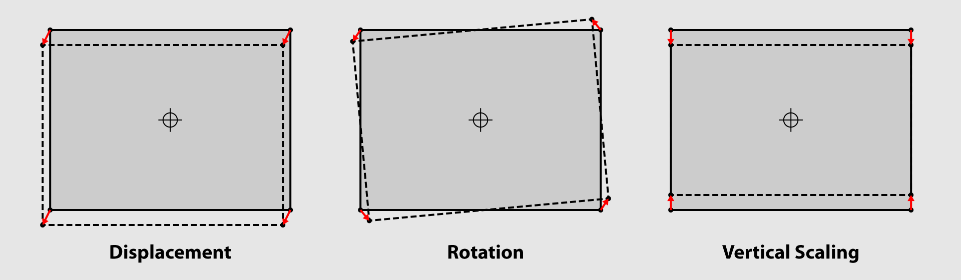
| The frame moves vertically and horizontally but does not rotate. The dimensions of the frame remain constant. The red arrows (corner movement vectors) all point in the same direction and are the same length. | The frame rotates about its centre point. The frame dimensions do not change. The red arrows point in different directions but are symmetrical around the centre point. | The frame stretches or squashes vertically around its centre point. The height of the frame changes, but not its width. The red arrows point up or down and are vertically symmetrical. |
Once we know the x and y offsets of each corner dot, we can compute displacement, rotation and vertical stretch using geometry.
Let’s consider a couple of simple examples. We assume that the these motions all occur around the centre point of the frame.
Calculating Displacement
Observe that for displacement the little red arrows all point in the same direction. If we add together and average these four arrows (vectors) we will get a measure of overall displacement of the frame. On the other hand, observe that for rotation and vertical stretch the arrows would cancel each other out if added together.
Hence, averaging the offsets of all four corners will generate a value for displacement while at the same time cancelling out any effects of rotation or vertical stretch.
Calculating Rotation
Notice that for (anti-clockwise) rotation the arrows in the left corners point downwards while those in the right corners point upwards. If we subtract the vertical offsets of adjacent (left and right) corners we will get a measure of the rotation of the frame while at the same time cancelling out the effects of displacement and vertical stretch.
The same process can be applied to calculate vertical scaling by subtracting the vertical offsets of vertically adjacent corners.
Transforming the Frame Image
Armed with values for displacement, rotation and vertical scaling, we can then plug these into what’s known as an affine transformation. An affine transformation uses a 3 x 3 matrix of numbers to convert one digital image into a new image where the positions of the pixels are shifted to effect a displacement, rotation and scaling of the image.
In the case of our scanned film frames, we use this affine transformation to apply inverse values of displacement, rotation and vertical scaling to those we measured. This will cancel out the motions caused by the frame jitter resulting in a more stable video image.
Final Reduction to PAL SD+ Frame Size
When a digital image is reduced in size or rotated, the pixels in the new image are computed from a combination of pixels in the source image. In other words, more than one pixel in the source image contributes information to each pixel in the output image. This blending of pixels can introduce subtle blurring of the image, so it makes sense to minimise the number of these transformations.
For this reason I decided to do the final scaling from the 2K frame size to PAL SD+ at the same time that the jitter is being corrected — i.e. as part of the same affine transformation.
In the next post we will deal with a few odds and ends which arose as part of this stabilisation exercise.