In the earlier post[1] about downsampling the kine scans from 2K to “PAL SD+”, we established the need to know the minimum dimensions of the video raster, which varies slightly in width and height over the duration of a reel. The final cropping boundary for a PAL SD video needs to fall within the minimum video raster size so that we get nice clean edges on the video frames.
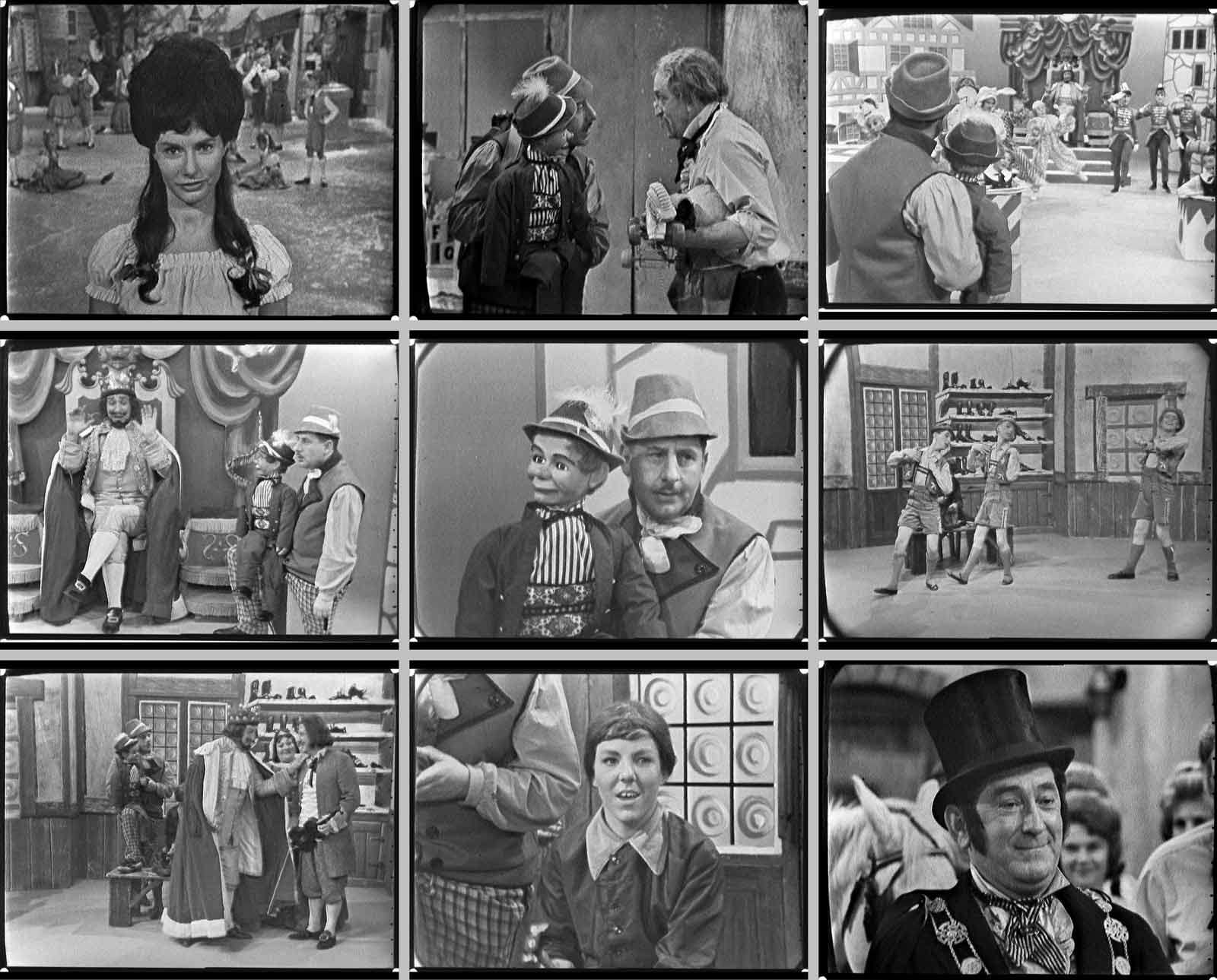
This required scrubbing through the 2K scan and measuring the video raster dimensions at the locations where the raster seems to have a noticeably smaller size. The following table contains some measurements for “Marianne” (1963):
| Timecode | Video Raster Maximum | Video Raster Minimum | Video Raster Position (left-right) |
||
|---|---|---|---|---|---|
| Width (px) | Height (px) | Width (px) | Height (px) | ||
| 00:10:00 | 1955 | 1500 | 1926 | 1477 | slight left |
| 1:48:00 | 1960 | 1501 | 1920 | 1465 | centre |
| 5:11:13 | 1972 | 1500 | 1930 | 1460 | hard right |
| 9:25:00 | 1962 | 1500 | 1887 | 1467 | hard right right dots |
| 15:00:00 | 1970 | 1493 | 1931 | 1473 | medium right right dots (closer to frame edge) |
| 19:18:00 | 1967 | 1485 | 1924 | 1448 | slight right |
| 19:38:00 | 1985 | 1480 | 1940 | 1434 | medium right |
| 20:42:00 | 1976 | 1477 | 1933 | 1437 | slight left |
| 33:42:00 | 1972 | 1501 | 1941 | 1470 | medium left |
| 35:20:00 | 1971 | 1503 | 1908 | 1456 | middle |
| 38:26:16 | 1986 | 1499 | 1947 | 1448 | medium right |
| 45:42:10 | 1975 | 1484 | 1912 | 1448 | hard left |
| 46:16:17 | – | – | 1923 | 1460 | medium left |
| 50:32:15 | 1963 | 1495 | 1922 | 1463 | hard right (almost) |
| 52:06:14 | 1986 | 1490 | 1939 | 1466 | hard right |
| Limits | 1955 | 1477 | 1947 | 1477 | |
Table 1: Measured maximum and minimum dimensions of the video raster at various points in the “Marianne” 2K scan. Also noted in the last column is the position of the video raster within the scan frame. Clearly it moves around a lot! The last line shows the limits of the dimensions in each column.
You might be wondering why there are both minimum and maximum dimensions for the video raster at each particular time code. This is because the video raster is not a perfect rectangle, in fact far from it. This was analog technology, not the precise digital technology of today. The video raster not only moves around during a reel, but also changes shape, often depending on which particular camera is generating the image. The edges of the raster can be curved and slanted. The maximum dimension is noted, but it is the minimum dimension which will determine where the image can be cropped to ensure a clean edge.
Choice of Final Crop Dimensions
From Table 1 above we can conclude that:
1477 ≤ Final Crop Height ≤ 1477
In the end I decided on a crop width of 1950 pixels and height of 1477 pixels. Note that the aspect ratio of these numbers is 1.32:1 — quite close to the theoretical 4:3 for black and white television.
We can plug these values into the calculation script mentioned in the earlier post[2].
This tells us that the pixel dimensions of the video after downsampling will be:
Working target width: 756
Working target height: 607
For this particular reel this is what we have been calling PAL SD+, i.e. PAL SD plus allowance for overscan beyond the edges of the video raster. The script also tells us that the aspect ratio of this downsampled image is:
Working Target aspect ratio: 1.2462
And it tells us the horizontal and vertical scale factors required to do this downsampling:
Horizontal scale factor: 0.369231
Vertical scale factor: 0.38998
Finally it reports the assymmetry of this scaling:
Scaling assymmetry (h/v): 0.9468 (-5.32%)
This last figure is interesting. It’s telling us how much we are changing the shape of the image compared to what is on the kine scan — we’re squashing it horizontally by over 5%. That seemingly large assymmetry is due to the effect of Pixel Aspect Ratio, discussed previously. We are downsampling for PAL SD which has non-square pixels and a PAR of 1.0666 (which we calculated in the post “The Relevance of Pixel Aspect Ratio”[3]).
So if we multiply 0.9468 x 1.066666 we get 1.0099. This is the net amount of stretching of the image that will occur when a video display device stretches the pixels by the PAR. i.e. there will be less than a 1% distortion of the shape of the original video raster. This is not bad considering how “approximate” was the analog TV video system.
In the next post we will look at adjusting framing and levels in Final Cut Pro X.
[1][2] The Mathematics of Downsampling the High Definition Scans for PAL SD