In this post we’re going to get a bit more technical and look into how these film copies (“kines”) were made from the original television productions. We’re going to delve into some technical history of film recordings at GTV9 circa 1960.
I would like to acknowledge the assistance of former GTV9 engineers Ian Douglas and Andrew McKean in providing technical details of the film recording system.
Technical Parameters of the Australian Television System Circa 1960
The Australian black and white television system circa 1960 delivered 25 television “frames” per second. Each television frame had 625 scan lines. These 625 scan lines were split between two “fields”, with two successive fields making up each frame (hence 50 fields per second). Consequently each field contained only half of the 625 scan lines for each frame — i.e. around 300 scan lines per field. The relevance of this will become clear in a moment.
Recording Video to Film
For the first few years, the only way of recording a television production was to make a copy on film. Videotape did not arrive at GTV9 until 1959, but due to the high cost of the tape, it was not considered as an archival medium.
How then were film copies made from television?
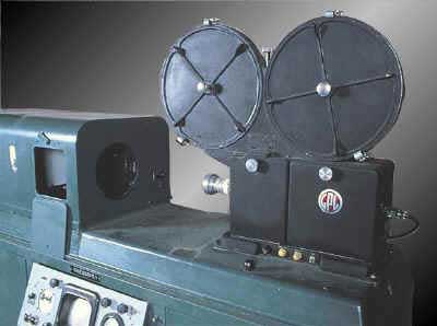
GTV9 operated two Film Recorders made by General Precision Laboratories in the USA. These consisted of a Kodak cine camera positioned in front of a CRT display (i.e. a television screen). The film was run at 25 frames per second (instead of the standard 24 frames per second used in cinemas) to synchronise with the 25 frames per second of the television image.
Compromises Required for Synchronising the Film and Video
Consider for a moment the difficulty of copying a television image to movie film. The film needs to be kept stationery while the television image is “painted” onto the CRT display by the moving electron beam. Then the film needs to be rapidly moved down by one film frame, ready to receive the next television frame. Movie film has always worked like this — a period during which a frame is exposed (the camera shutter open) followed by a rapid “pull-down” of the film (camera shutter closed). However, in the case of copying television images to film, the television system has its own relentless timing to which the film movement has to adhere.
In the film recording system used at GTV9, it turned out to be impractical to record every television frame to film and then physically “pull-down” the film in the few milliseconds of “vertical blanking” between frames.
Consequently, to allow sufficient time for the film “pull-down” to happen between film frames, only alternate television fields were recorded to film — i.e. effectively only half the “data” in each television frame was recorded to film.
This means that the vertical resolution of the image on the film is only about half the standard 625 lines, or roughly 300 lines. The horizontal resolution, however, was quite high.

Recording of Audio to the Film Soundtrack
The audio was recorded onto the film using an optical soundtrack, either at the same time as the video recording (using “variable density” recording), or via a separate optical sound-on-film recorder (using “variable area” recording). The picture and sound films were then combined in the film laboratory to create a “release print”.
It is generally considered that a 16mm optical soundtrack has an upper bandwidth of around 6kHz — not exactly the kind of audio quality to which we are accustomed today from digital media. Nevertheless, with a bit of equalisation, these old optical soundtracks can sound reasonable.
Summary
As you can see, we are dealing with both picture and sound elements which are far from ideal by modern day standards — a video resolution of less than 300 lines vertically, and an audio bandwidth of only 6kHz.
One of the challenges of this project is to see just how good a result can be achieved from transferring these old film recordings to the digital realm. Will a copy on DVD do justice to these recordings? The answer of course is yes. PAL SD (“Standard Definition”) DVD format has a vertical resolution of 576 pixels and horizontal resolution of 720 pixels. It’s going to provide more than adequate resolution to preserve the much lower resolution images on the film.
In the next post we will look at initial experiments in digital telecine.
ADDENDUM — The Really Technical Stuff
For those with an engineering bent, I reproduce here edited versions of the complete technical descriptions obtained from former GTV9 engineer Ian Douglas. Ian dusted off a technical paper written 56 years earlier to provide the following details.
The recording equipment came from the USA, and was manufactured by General Precision Laboratories (GPL). We had two machines, and each had its own “personality”. They were originally made for the US 60Hz 525 line TV system, and had been extensively modified for the Australian 50Hz 625 line system.
The biggest problem was the mechanical transport of the film. In the USA system they adhered to a film speed of 24 frames per second, as used in theatrical projection systems. With 30 interlaced TV frames per second they “threw away” six of those frames, and used the resulting time slack for the film pull down.
The mechanical claw film transport system was very difficult to engineer. The large accelerations involved set up vibrations which caused fatigue fractures in the lightly built metal parts. During exposure the film was held stationary by a vacuum pump system.
The Australian TV system which used 25 video “frames” per second required a different approach. The GPL equipment for the Australian 625 line 50Hz TV system, used only one of the interlaced scans, and used the period of the other interlaced scan (approximately one fiftieth of a second) to move the film. The vertical definition, was thereby only 312 and a half lines — i.e. half the normal resolution (625 lines) of the standard TV system.
Using the reduced number of lines by dropping alternate interlaced fields had the advantage of avoiding the problem of displacement blurring from the second field when there was motion in the picture.
With the video waveforms coming straight out of the studio equipment, the horizontal definition was quite high, and was boosted as well.
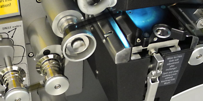
To fill in the gaps between the lines the spot on the screen was vertically broadened to fill 75% of the empty space between the lines using a 22 MHz “spot wobble” system. The system used a kinescope tube with a P11 blue/ultra violet phosphor having a long decay time, and there was a lot of extra circuitry used to equalize the exposure across the screen.
In relation to the audio recording, the GPL equipment had a variable density recording device built in to the camera. In addition, we had two Stancil Hoffman tape recorders which recorded on to a magnetic tape configured as a 16mm sprocketed film. These recorders were locked to the mechanical side of the film recorder using selsyn motors, and they were used as an audio backup, in case the variable density track wasn’t of good enough quality. In that event you could get the film recording magnetically striped, and synchronously record the sound back on to it from the 16mm tape. You had to mark the film by punching a hole through a start frame so you could re-establish sound sync.
A few months after the start of operations, we bought a separate variable area recorder, which was, I think, second hand. We were seeking better sound quality. The variable area system has a sort of “automatic gain control” device that blackens much of the unused area of the soundtrack, which would otherwise be white (clear) to cut the noise from dirt on the film. This meant two passes, recording the vision first with no sound exposure, and then the variable area track from the Stancil Hoffman tape on a second pass through the sound recorder. We must have been able to synchronise this unit, although I can’t recall precisely how we did so. I have a vague recollection that the spares included a selsyn motor, and we probably pressed that into service.
I think a lot of this was aimed at more copies for network use, as we originally recorded direct positives using a negative image on the CRT, and that gives only one copy. We could also make negatives by putting a positive image on the CRT, put the variable area sound track on the negative, and then get the film laboratory to run positives from the master negative. Variable area sound gives much better quality in the negative to positive process. The sound would also be recorded on the negative as a negative version.
As far as TV recording was concerned, when we first started it was all a bit haphazard. The first recording I made of the opening ceremony of GTV9 on 19th January 1957 was rather washed out. Later on Lindsay Sage and I worked out better ways of standardising what we were doing.
We set our screen exposures using the window generator set to correct voltage levels. One of the various possible outputs gave a picture with half white one side, and half “black” on the other, and we used a light meter to measure the brightness of the screen. As we were recording a negative image the brightest part was our black in the final film for which the density was to be 1.75. The faintest part was to result in a density of 0.12. That gave a contrast ratio of 43 to 1, which I noted in my paper “projects well in telecine systems, but not in normal theatres”. We would expose test strips of this signal, and when we went to Herschells Film Laboratories to develop the film we would develop the test strips first and measure them on a densitometer, adjusting the film speed through the processing machine until we got the right result. The short exposure time resulting from the high speed spot was subject to “reciprocity failure”, so the process was non-linear. That was why we had to actually work off the final results.
That’s a long story, but what it means is that fairly early on we went to considerable lengths to control both the exposures, and the development of the film. Certainly once we started a recording we didn’t adjust anything except to keep it as it should be, and these early kinescopes should therefore have quite consistent levels, with the only changes being those occurring in the picture itself due to its content.